Autonomous Steering System (ASS)
The ASS interfaces with the vehicle’s driver operated steering system to replace driver input through electromechanical actuation. Functionally, the ASS needs to apply force to the steering toe links, allowing the vehicle to turn in the desired direction driverlessly.
Rules Overview
Below are rules from the 2025 FSAE Driverless Supplement that constrained vehicle retrofitting solutions for ASS.
DT.2.1 Steering Actuation
DT.2.1 defines that manual steering must always be possible when the vehicle is out of a driverless state and that driverless accusation can only take place when the vehicle is ready to drive.
DT.2.2 Actuator Decoupling
DT.2.2 defines that driverless steering action can be decoupled from manual steering but no part can be removed from the system.
System Background & Design Approach
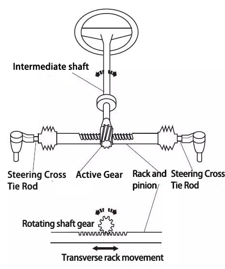
FSAE Steering Diagram (reference)
- Linear rack actuation
This can be achieved through a number of methods, including use of another driven steering rack, a linear actuator, or a ball screw as a form of linear movement. All approaches mount to and move the rack linearly to autonomously turn the vehicle.
- Rotational actuation of the column
This is achieved through direct drive by a motor. Utilizing sprockets, hubs, or pulleys to rotate the column as the motor rotates to autonomously move the vehicle.
Based on the specified rules, the system must be backdrivable or steerable by a human driver. This can be assured by having low friction and proper alignment in the system.
A sensor must also be implemented to control the angle of steering. This ensures that accurate trajectory commands from the controller are sent to the physical vehicle.
Our Implementation
The Autonomous Steering System (ASS) actuates the vehicle’s steering rack through a linear drive, designed around a ball screw mechanism. The system was developed to meet performance goals of delivering sufficient output torque, achieving full lock-to-lock steering travel within one second, and maintaining backdrivability.
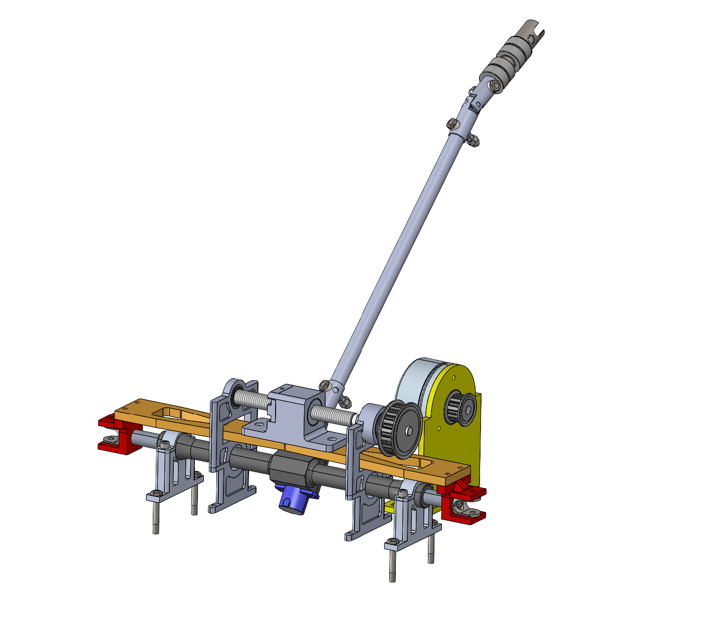
ASS 3D Model
To ensure responsive actuation, a 1-second target for full lock-to-lock travel was established. Based on the pinion diameter and the total linear travel required at the rack, the necessary rack speed was computed. This was then converted to an equivalent rotational speed.
A ball screw with a lead of 5 mm/rev and an efficiency of ~90% was selected. Steering requires high force to move the rack under load. Thus, a low lead and higher efficiency increases mechanical advantage, allowing the motor to generate sufficient linear force with lower torque. Furthermore, a 1.8 pulley ratio was selected to further reduce the input torque needed and allow for the use of a smaller motor.
The torque required at the screw input was calculated using: T = F_load * L / 2π⋅η
F_load, the axial force needed to move the rack was calculated by dividing the maximum static steering torque by the pinion radius. L represents the rack lead, and η is the efficiency of the ball screw multiplied by the efficiency of the rack.
Similarly, the speed required at the screw input was calculated using: w_motor = v_rack * R * 60 / L
This includes the linear rack speed multiplied by the pulley reduction ratio and divided by the ball screw lead.
The ball screw ends were machined to interface with both the driven pulley and end bearing supports. To minimize rotational inertia and reduce axial bending forces, the ball screw was kept as short as possible, while still allowing full lock-to-lock rack travel. This compact design reduces deflection during operation and increases system stiffness.
As the motor rotates the ball screw, the ball nut translates linearly along the screw’s axis, converting rotational input into precise linear motion. Rigidly attached to the ball nut is a flat aluminum carriage plate, a component that spans across the top of the steering rack. Tabs were designed and machined to interface directly with the existing clevises on the ends of the rack. These tabs were bolted both to the clevis joints and to the carriage, forming a rigid, bolted linkage between the ball nut and the steering rack.
As the ball nut moves left or right along the screw, it pushes or pulls the clevises through the rigid carriage. Since the clevises are fixed to the rack, this causes the entire steering rack to shift laterally, translating into angular motion at the wheels via the tie rods and steering arms. This mechanism effectively allows the autonomous system to control the front steering angle.
All structural mounts for the motor, ball screw, and end bearings were CNC-milled from aluminum stock, designed with a focus on minimizing vertical profile and keeping the system’s center of force application as low as possible. By placing the screw and motor axis near the base plane of the vehicle chassis, the design reduced cantilevered moment and allowed for easier backdrivability.
To monitor steering position in real time, a rotary encoder was mounted at the base of the steering column. This sensor provides continuous feedback for closed-loop control of the ASS, ensuring that the controller can track and correct the steering angle dynamically during autonomous operation.
The design maintains backdrivability, due to the low-lead, high-efficiency ball screw and the minimal friction within the system. Because the system allowed for minimal resistance to be manually overridden due to the high-efficiency ball screw and minimal system friction, no dedicated mechanical decoupling system was added.