Autonomous System Brake (ASB)
The ASB is responsible for slowing the vehicle to a stop. It includes an Emergency Braking System (EBS) to stop the vehicle in the case of a safety/power failure or if the emergency stop RES is hit.
Rules Overview
Below are rules from the 2025 FSAE Driverless Supplement that constrained vehicle retrofitting solutions for ASB.
DT.3.1 Driverless System Brake
DT.3.1.1 defines key limits for ASB including the mounting area and requirement that manual braking must to always be possible.
Mounted inside the volume defined in DT.2.3.a
Mounted in one of the two: near the DSMS or on the top side of the vehicle between the Front Bulkhead and Front Hoop close to the vehicle center line
Near each other
Protected against unintended actuation (being hit by a cone) while driving
Marked with “Brake Release”
Fitted with a red handle
Able to work without electrical power
Operated by maximum two simple push/pull and/or turning actions, the order and direction of these actions must be shown next to the Deactivation Points
DT.3.1.2 defines key requirements for the deactivation points for the ASB release including mounting location and basic requirements.
DT.3.2 Emergency Brake System (EBS)
DT.3.2 defines key requirements for the Emergency Brake System (EBS) including that it must use stored mechanical energy and trigger in an emergency state.
DT.3.2.2-4 defines the function and state behavior required by EBS.
DT.3.2.5 defines the base system requirements for EBS.
System Design
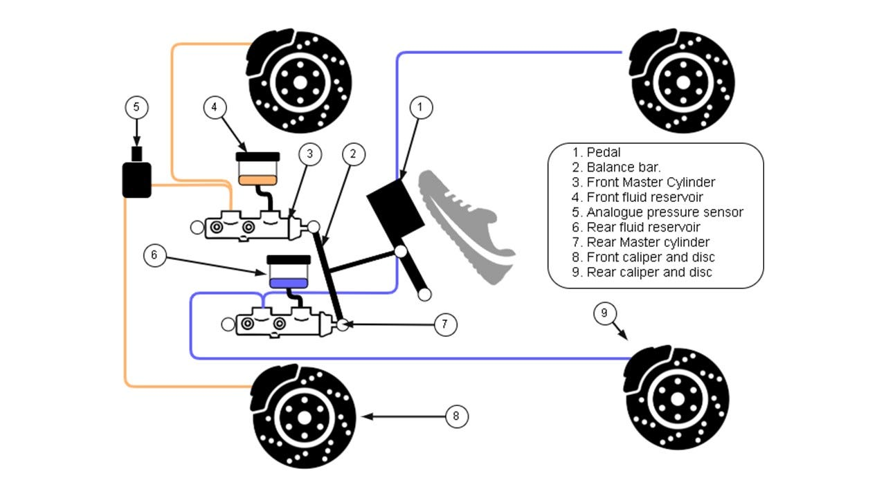
FSAE Braking Diagram (reference)
FSAE brakes begin with two master cylinders. These master cylinders are mounted on the manual brake pedal. When the driver pushes the pedal down, the master cylinders compress. Additionally, each wheel on the vehicle has brake calipers mounted on its hub, these connect hydraulically to the master cylinders. When the master cylinders are compressed, brake fluid pushes to the calipers, compressing the brake pads to lock the wheels.
The main requirement of Autonomous System Brake (ASB) can be fulfilled by regeneration braking. The motors are sent negative torque commands which are used to decelerate the car, serving as a driverless form of braking.
The addition of the EBS required by the rules must utilize mechanical energy and not inhibit the compression of the brake pedal manually. There are two main design approaches to EBS:
Hydraulic integration with the existing brake lines
Addition of two driverless-specific master cylinders that hydraulically interface with the pedal master cylinder through 3-way valves allowing the side with the higher pressure to flow to the outlet. The line with the lower pressure is sealed off, allowing for pressure to build up and lock the calipers based on which master cylinder is currently compressed.
Physical actuation of the pedal
Actuation of the pedal involving pneumatics or other mechanically stored force to physically move the brake pedal and compress the existing pedal master cylinders.
After EBS is triggered, the braking must be released via manual release valves. Per the rules these must be mounted on the top face of the vehicle near the center line such that anyone can release brakes.
Implementation
Regular braking throughout a driverless run fulfilled by regenerative braking.
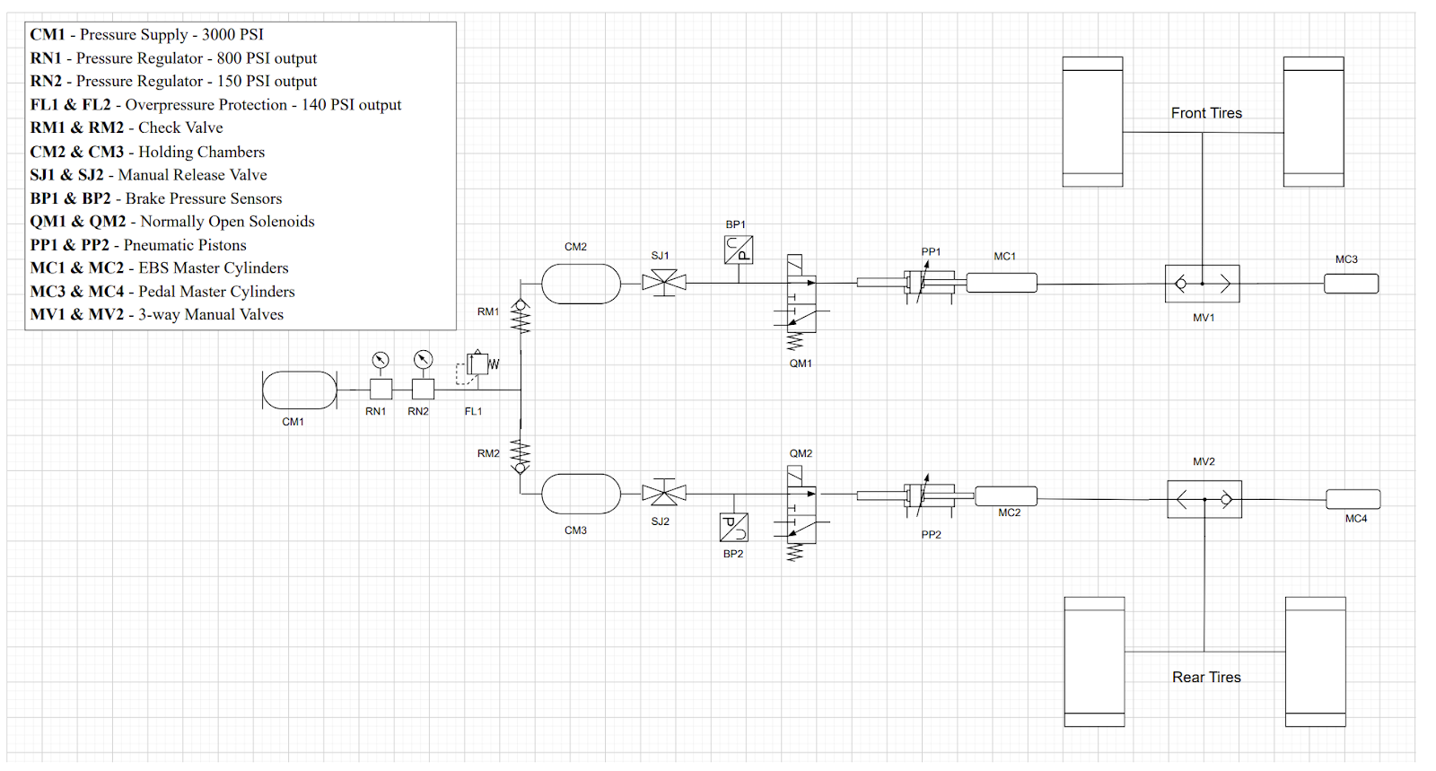
Carnegie Mellon Racing Driverless and Manual Brakes Integration Schematic
Shared Pneumatic Supply
Power Supply - Large Air Tank
Pressure Regulator - 800 PSI Output
Pressure Regulator - 150 PSI Output
Over Protection - 140 PSI Output
Tee Fitting - Splits into separate front and rear braking lines for redundance
Separate Pneumatic Systems
Check Valves - Ensures no back flow from holding chambers to power supply
Holding Chambers - Holds air to ensure redundancy if pressure supply fails
Manual Release Valves - Remove air from one side of the line
Pneumatic Pressure Sensors - Allows for continuous monitoring of pressure within the lines
Normally Open Solenoids - Allows air travel when the vehicle has no power.
Pneumatic Pistons - When pressurized, these actuate directly on the EBS master cylinders
EBS Master Cylinder - Pushes brake fluid down to 3-way valve
Separate Hydraulic Lines
3-way valve - Fluid from both the EBS and Manual Master Cylinders meet. The highest pressure flows through
Brake Caliper - Outlet of 3-way valve directs brake fluid to the calipers which lock the wheels to stop the vehicle
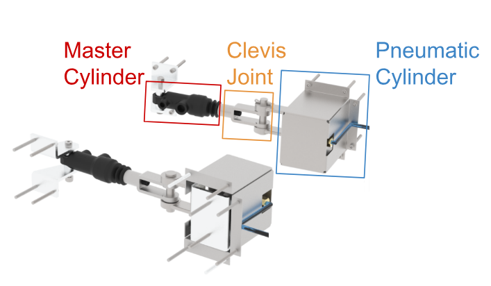
EBS Pneumatic and Master Cylinder Interface Model
The EBS master cylinders are compressed by the pneumatic cylinders which are triggered by normally open solenoids.
The brake lines from the EBS master cylinders meet with the brake lines from the manual master cylinders mounted on pedals at a 3-way valve. The 3-way valve allows the input with the highest pressure flow through to the output. This enables the switch between EBS and manual braking based on which side has a higher pressure.
The air is exhausted from the system through a pair of 3-way manual release valves mounted on the dashboard near the center line of the car in alignment with rule specifications.