Coloring Module Concepts
Overview
RGB cameras provide a source color information. Though the Stereolabs ZED cameras also have stereoscopic capability, the pipeline avoids any depth processing due to latency concerns. Instead cameras are used purely for color information.
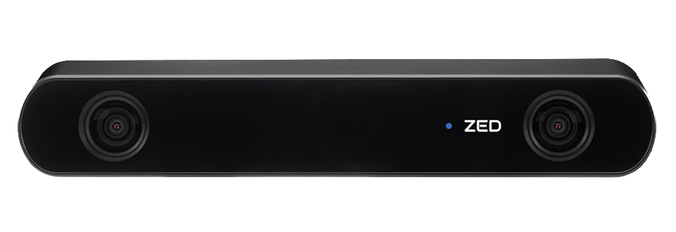
Stereolabs ZED2 Camera used on 24a
Goal of the Coloring Module
The Coloring Module aims to apply RGB color information from cameras to classify cones coming in from the LiDAR Module by color. Color classification delineates the sides of the track and allows Path Planning and Controls to do higher-level processing.
Info
We use ROS2 to implement our pipeline. See Software Architecture for more information.
Our coloring module is housed in our custom ROS2 package, point_to_pixel.
Input: a set of uncolored cone centroids.
/cpp_conesinterfaces::msg::PPMConeArray
Output: a set of colored cone centroids passed down the pipeline to Path Planning and Controls.
/perc_conesinterfaces::msg::ConeArray
Algorithm

Algorithm diagram
Simplified Point to Pixel Mapping Algorithm
for each set of cone centroids / camera image do:
    YOLO v5 cone detection inference: bounding boxes of different color/size classes

    for each cone centroid do:
        transform to image space via transform matrix (see Direct Linear Transform below)

        if point is within a single bounding box classify as that color

        if point is in multiple boxes use a rough depth heuristic to pick one box

        else label the point as unknown
Notes
Point to Pixel Mapping makes the assumption that the cameras remain rigid with respect to the LiDAR at all times.
Our YOLO v5 is trained on data from Formula Student Objects in Context Dataset (FSOCO)
Depth heuristic uses the idea that the area of the bounding box roughly corresponds to depth
Direct Linear Transform (DLT)
What is DLT?
Direct Linear Transform (DLT) is the technique we use to solve for the static transform matrix from LiDAR to camera space. It consists a calibration sequence that uses a series of (at least 6) points identified by hand in both the LiDAR and camera frames and a mathematical formula to solve for the matrix.
Why use DLT?
It is insufficient to use geometric approaches, e.g, measuring or CAD to estimate the static transformation matrix from camera to LiDAR. This is due to a multitude of reasons, but primarily results from the difference between design and fabrication. DLT allows for an accurate transform to be calculated via calibration instead.
Figure: calibration setup consisting of many cones spread throughout at different heights and depths
Warning
This method is heavily dependant on a good calibration. If the sensors move relative to each other or if the calibration points weren’t picked at various depths / heights, the accuracy drops off steeply.